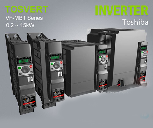
Capacity range
- Single phase 240V 0.2kW ~ 2.2kW
- Three phase 500V 0.4kW ~ 15kW
Variable Speed Drive VF-MB1 can drive elevator, lifting, conveyor, food & beverage processing, material handling, machine tool and various applications
Slim Shape body
Side-by-side installation flat Mounting Installations
Advance Motor Drive
Sensor-less permanent Magnetic motor, SPM/IPM and Induction Motor Drive Capability
Toshiba unique magnetic pole position detection
Simple panel
Setting dial, 4 keys, and 4 small LEDs with Green 7 segementes LEDs can be easy to set parameters and operations.
Dual rating (CT/VT)
Variable Speed Drive VF-MB1 can be used for the constant torque and variable torque applications by dual rating operation. if variable torque (fan and pump) require 15kW drives, it can be operated by 11kW rated of VF-MB1.
Constant torque application
The torque value of constant torque application require the high torque level of different motor speed for Conveyors, Machine tool, Food machine and Elevator
Variable torque application
The torque value of variable torque application such as Fan, Pump and HVAC require low torque until starts to operating speed (compressor is excluded)
Variable Speed Drive VF-MB1 Models
- VFMB1S-2002PL (1 phase 240V 0.2kW)
- VFMB1S-2004PL (1 phase 240V 0.4kW)
- VFMB1S-2007PL (1 phase 240V 0.75kW)
- VFMB1S-2015PL (1 phase 240V 1.5kW)
- VFMB1S-2022PL (1 phase 240V 2.2kW)
- VFMB1-4004PL (3 phase 500V 0.4kW)
- VFMB1-4007PL (3 phase 500V 0.75kW)
- VFMB1-4015PL (3 phase 500V 1.5kW)
- VFMB1-4022PL (3 phase 500V 2.2kW)
- VFMB1-4037PL (3 phase 500V 4kW)
- VFMB1-4055PL (3 phase 500V 5.5kW)
- VFMB1-4075PL (3 phase 500V 7.5kW)
- VFMB1-4110PL (3 phase 500V 11kW)
- VFMB1-4150PL (3 phase 500V 15kW)
Standard specificaitons
1-phase 240V
| Item | Specification | |||||
| Input voltage class | 1-phase 240V class | |||||
| Applicable motor (kW) | 0.2 | 0.4 | 0.75 | 1.5 | 2.2 | |
| Rating | Type | VFMB1S- | ||||
| Form | 2002PL | 2004PL | 2007PL | 2015PL | 2022PL | |
| Capacity (kVA) Note 1) | 0.6 | 1.3 | 1.8 | 3.0 | 4.2 | |
| Rated output current (A) Note 2) |
1.5 (1.5) | 3.3 (3.3) | 4.8 (4.8) | 8.0 (8.0) | 11.0 (11.0) | |
| Output voltage Note 3) | 3-phase 200V to 240V | |||||
| Overload current rating Note 2) | 150%-60 seconds, 200%-0.5 second (120%-60 seconds, 165%-0.5 second) | |||||
| Power supply | Voltage-frequency | 1-phase 200V to 240V – 50/60Hz | ||||
| Allowable fluctuation | Voltage 170 to 264V Note 4), frequency ±5% | |||||
| Required Power supply capacity (kVA) Note 5) |
0.8 | 1.4 | 2.3 | 4.0 | 5.4 | |
| Protective method (IEC60529) | IP20 | |||||
| Cooling method | Forced air-cooled | |||||
| Color | RAL7016 | |||||
| Built-in fi lter | EMC filter | |||||
3-phase 500V
| Item | Specification | |||||||||
| Input voltage class | 3-phase 500V class | |||||||||
| Applicable motor (kW) | 0.4 | 0.75 | 1.5 | 2.2 | 4.0 | 5.5 | 7.5 | 11 | 15 | |
| Rating | Type | VFMB1- | ||||||||
| Form | 4004PL | 4007PL | 4015PL | 4022PL | 4037PL | 4055PL | 4075PL | 4110PL | 4150PL | |
| Capacity (kVA) Note 1) | 1.1 | 1.8 | 3.1 | 4.2 | 7.2 | 11 | 13 | 21 | 25 | |
| Rated output current (A) Note 2) | 1.5 (1.5) |
2.3 (2.3) |
4.1 (4.1) |
5.5 (5.5) |
9.5 (9.5) |
14.3 (17.0) |
17.0 (23.0) |
27.7 (33.0) |
33.0 (40.0) |
|
| Output voltage Note 3) | 3-phase 380V to 500V | |||||||||
| Overload current rating Note 2) | 150%-60 seconds, 200%-0.5 second (120%-60 seconds, 165%-0.5 second) | |||||||||
| Power supply | Voltage-frequency | 3-phase 380V to 500V – 50/60Hz | ||||||||
| Allowable fluctuation | Voltage 323 to 550V Note 4), frequency ±5% | |||||||||
| Required Power supply capacity (kVA) Note 5) |
1.6 | 2.6 | 4.7 | 6.3 | 10.1 | 15.2 | 19.6 | 26.9 | 34.9 | |
| Protective method (IEC60529) | IP20 | |||||||||
| Cooling method | Forced air-cooled | |||||||||
| Color | RAL7016 | |||||||||
| Built-in filter | EMC fi lter | |||||||||
Note 1. Capacity is calculated at 220V for the 240V models, at 440V for the 500V models.
Note 2. It is a value when the inverter overload characteristic selection (parameter aul) is the constant torque characteristic.
Value in ( ) for the variable torque characteristic.
The output current must be reduced according to the PWM carrier frequency, ambient temperature and supply voltage.
Note 3. Maximum output voltage is the same as the input voltage.
Note 4. At 180V-264V for the 240V models, at 342V-550V for the 500V models when the inverter is used continuously (load of 100%).
Note 5. Required power supply capacity varies with the value of the power supply side inverter impedance (including those of the input reactor and cables).
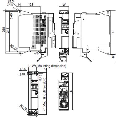
Dimension
| TypeForm | Input phase |
Voltage class [V] |
Capacity [kW] |
W [mm] |
H [mm] |
D [mm] |
W1 [mm] |
H1 [mm] |
D2 [mm] |
H2 [mm] |
Weight [kg] |
| VFMB1S-2002PL | 1 | 240 | 0.2 | 45 | 270 | 232 | 29 | 258 | 0 | 47 | 1.7 |
| VFMB1S-2004PL | 1 | 240 | 0.4 | 45 | 270 | 232 | 29 | 258 | 0 | 47 | 1.7 |
| VFMB1S-2007PL | 1 | 240 | 0.75 | 45 | 270 | 232 | 29 | 258 | 0 | 47 | 1.8 |
| VFMB1S-2015PL | 1 | 240 | 1.5 | 60 | 270 | 232 | 42 | 258 | 0 | 47 | 2.1 |
| VFMB1S-2022PL | 1 | 240 | 2.2 | 60 | 270 | 232 | 42 | 258 | 0 | 47 | 2.2 |
| VFMB1-4004PL | 3 | 500 | 0.4 | 45 | 270 | 232 | 29 | 258 | 0 | 47 | 1.8 |
| VFMB1-4007PL | 3 | 500 | 0.75 | 45 | 270 | 232 | 29 | 258 | 0 | 47 | 1.9 |
| VFMB1-4015PL | 3 | 500 | 1.5 | 45 | 270 | 232 | 29 | 258 | 0 | 47 | 1.9 |
| VFMB1-4022PL | 3 | 500 | 2.2 | 60 | 270 | 232 | 42 | 258 | 0 | 47 | 2.2 |
| VFMB1-4037PL | 3 | 500 | 4.0 | 60 | 270 | 232 | 42 | 258 | 0 | 47 | 2.4 |
| VFMB1-4055PL | 3 | 500 | 5.5 | 150 | 220 | 232 | 130 | 210 | 0 | 12 | 4.3 |
| VFMB1-4075PL | 3 | 500 | 7.5 | 150 | 220 | 232 | 130 | 210 | 0 | 12 | 4.3 |
| VFMB1-4110PL | 3 | 500 | 11 | 180 | 310 | 232 | 160 | 295 | 0 | 20 | 6.8 |
| VFMB1-4150PL | 3 | 500 | 15 | 180 | 310 | 232 | 160 | 295 | 0 | 20 | 6.9 |


